
Electronics
- Electronics
- 16-port plant monitor
- Snake enclosure monitor
- adjustable-height desk
- wii-motion quad copter
- Flashing a bricked motherboard bios
16-port plant monitor
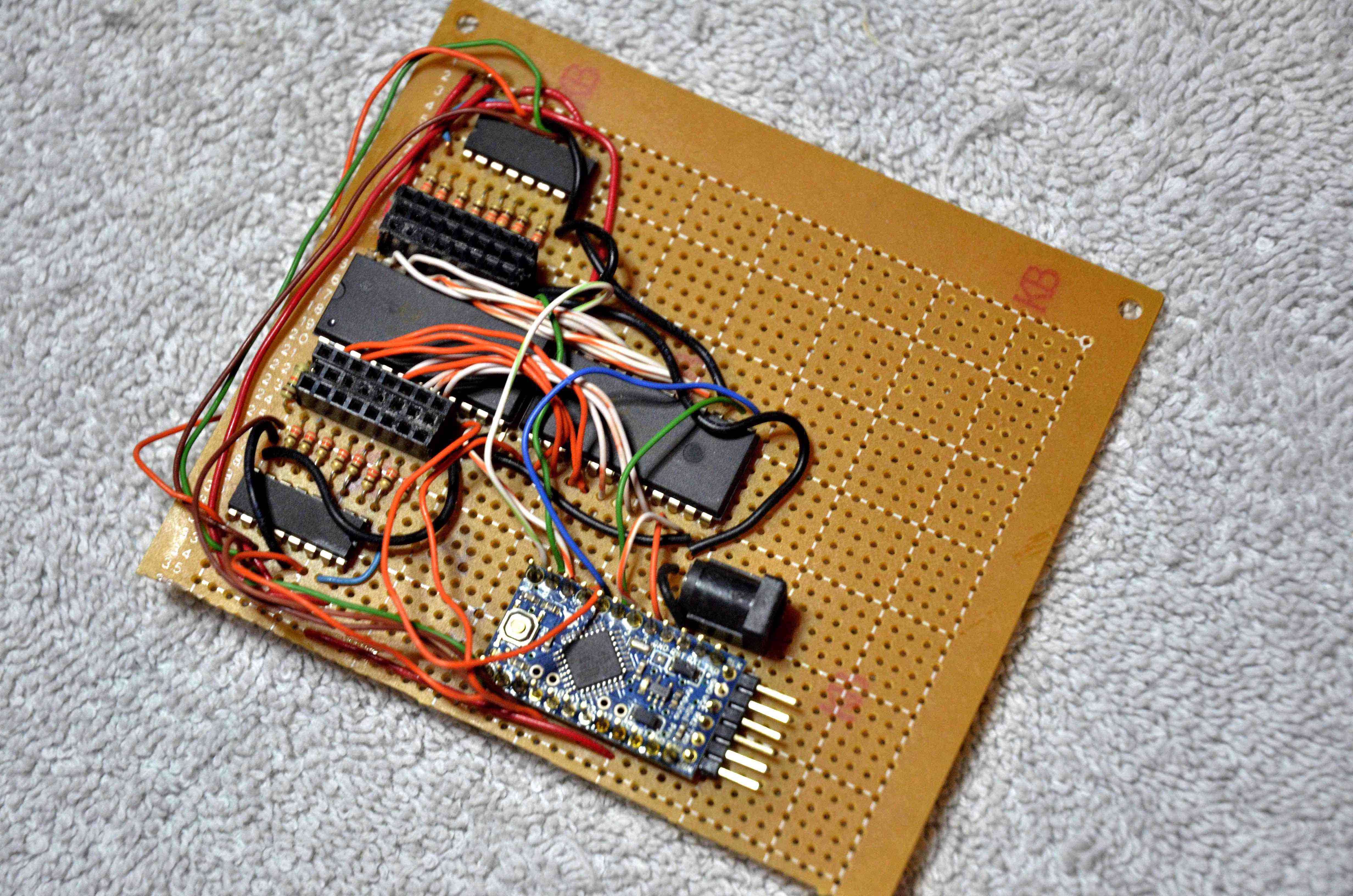
This project was created when we found that some moisture sensors consumed their batteries in just a week if left in the plant continually. there were had about 60 total moisture sensors, so changing batteries at that pace wasn’t practical. I pulled the moisture sensors apart, and used ethernet wire to connect them to an Arduino, in order to make it possible to provide external power. There are a lot of plants to look at, so I ended up using a couple of 16-port multiplexers, to allow me to address up to 16 sensors from a single Arduino, as well as two 8-bit shift registers, to allow me to light an LED on each of the moisture sensor sticks.
Here’s the github repository and a couple of photos.
Here it is, mounted on perfboard:
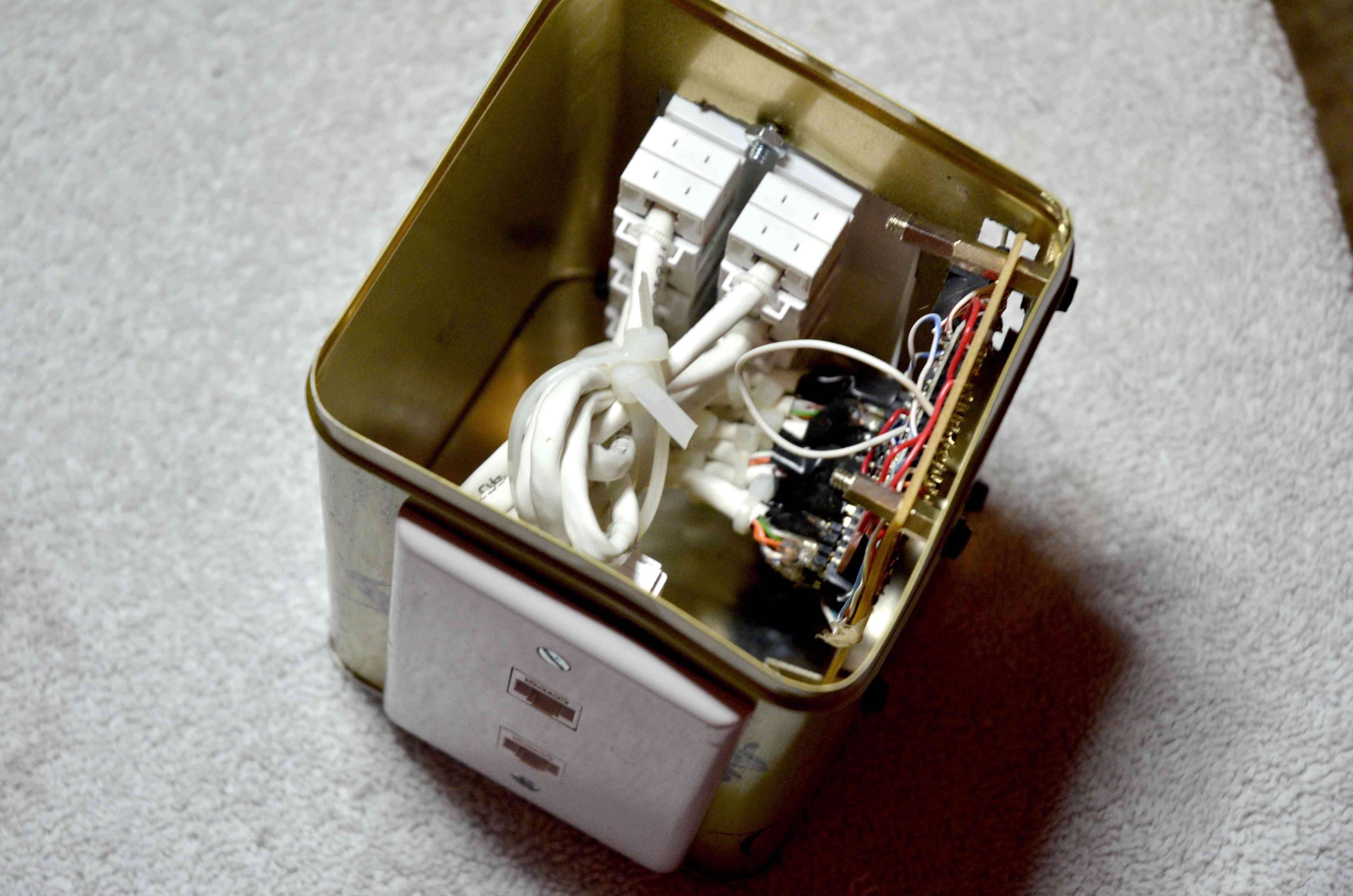
 Here it is, assembled:
Snake enclosure monitor
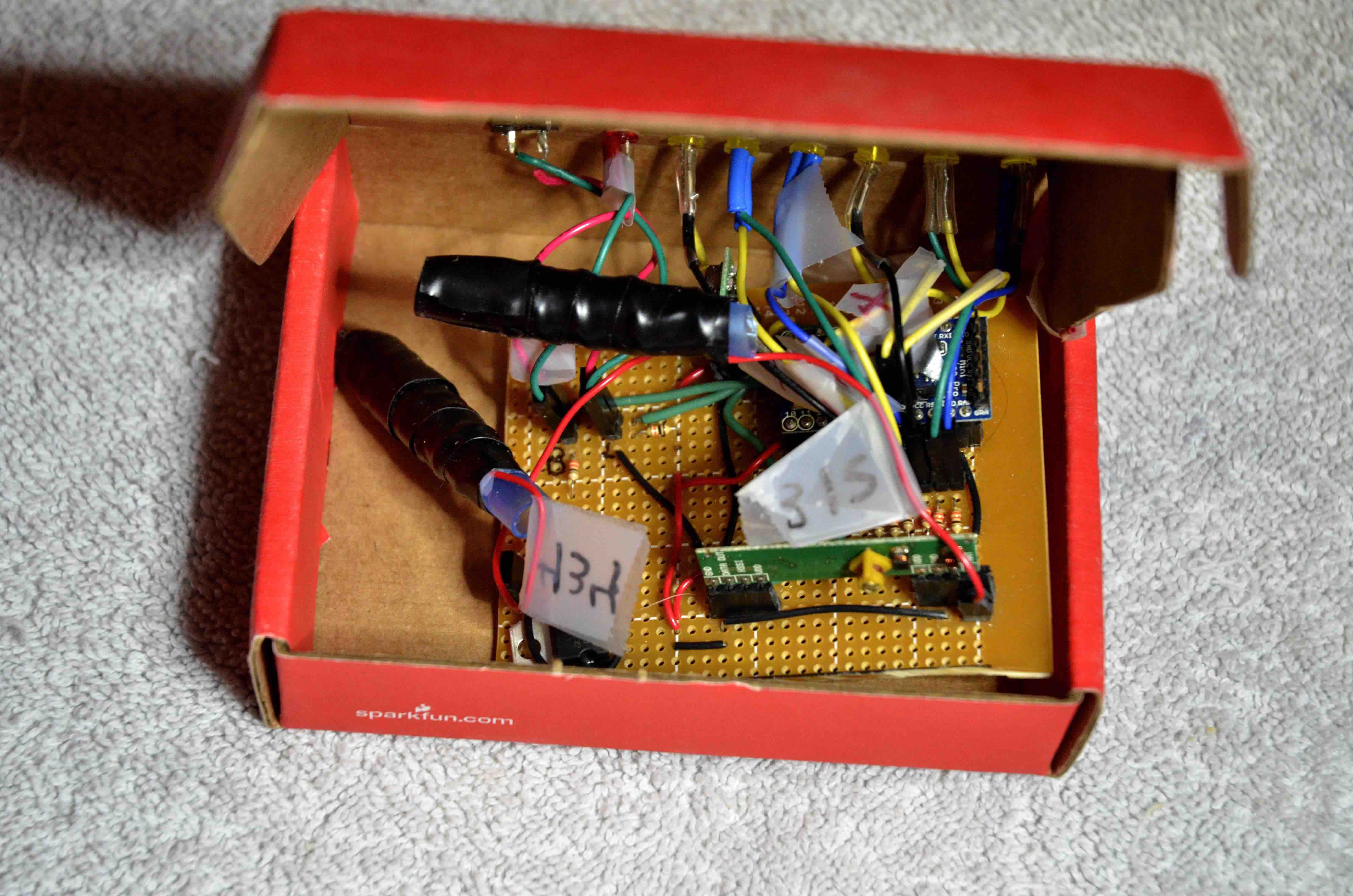
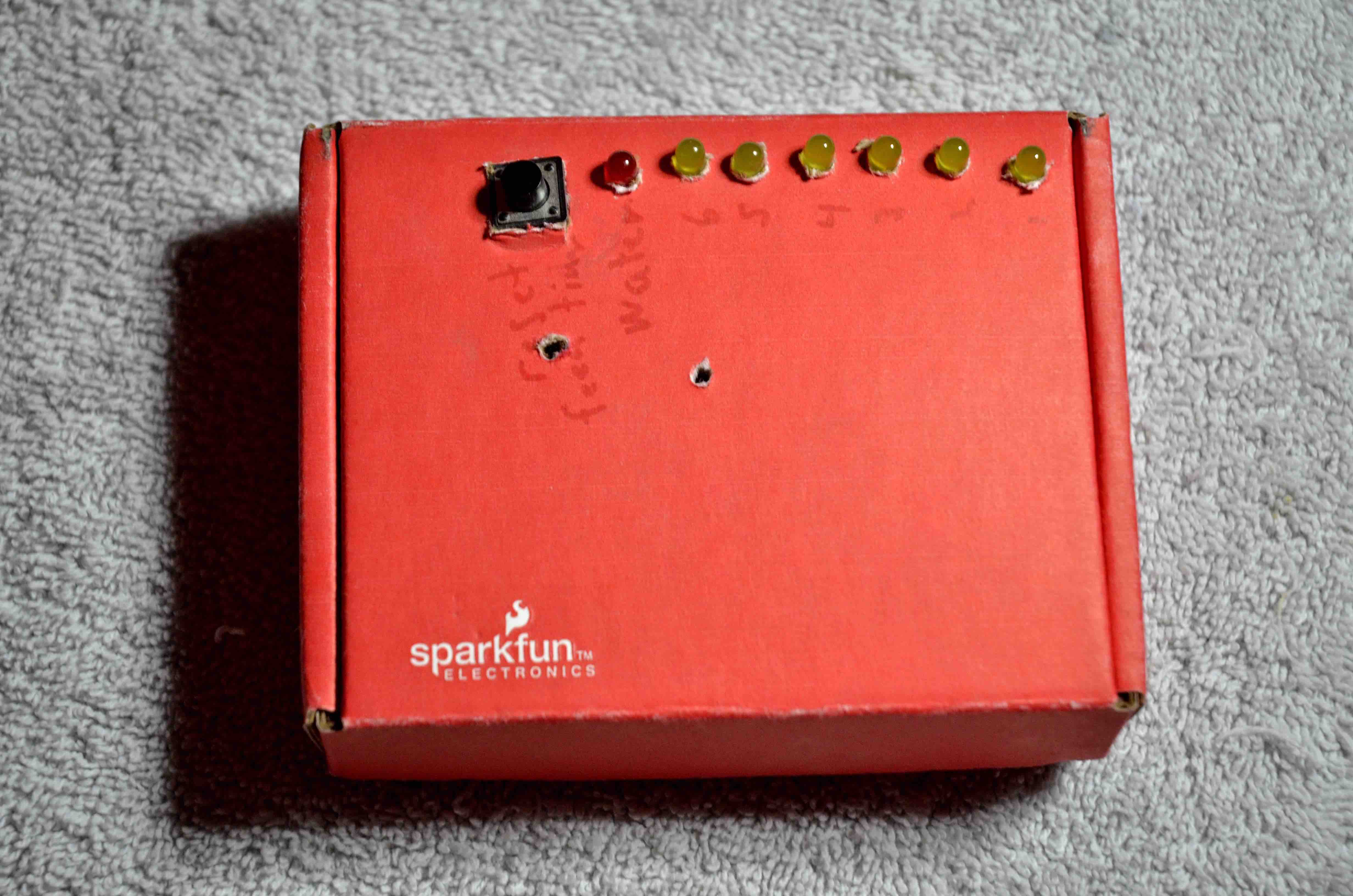
This project was created, to ensure that we remembered to feed snakes, once per week, and to make sure that, whoever fed them could signal to the rest of us, that they had been fed. It has six leds, and lights one up each day. On the seventh day, the six leds start blinking. Additionally, there is a simple moisture sensor, that runs into the water bowl, which will blink separately, when the water bowl is dry.
Here’s the github repository and a couple of photos.
The Perfboard:
Assembled:
adjustable-height desk
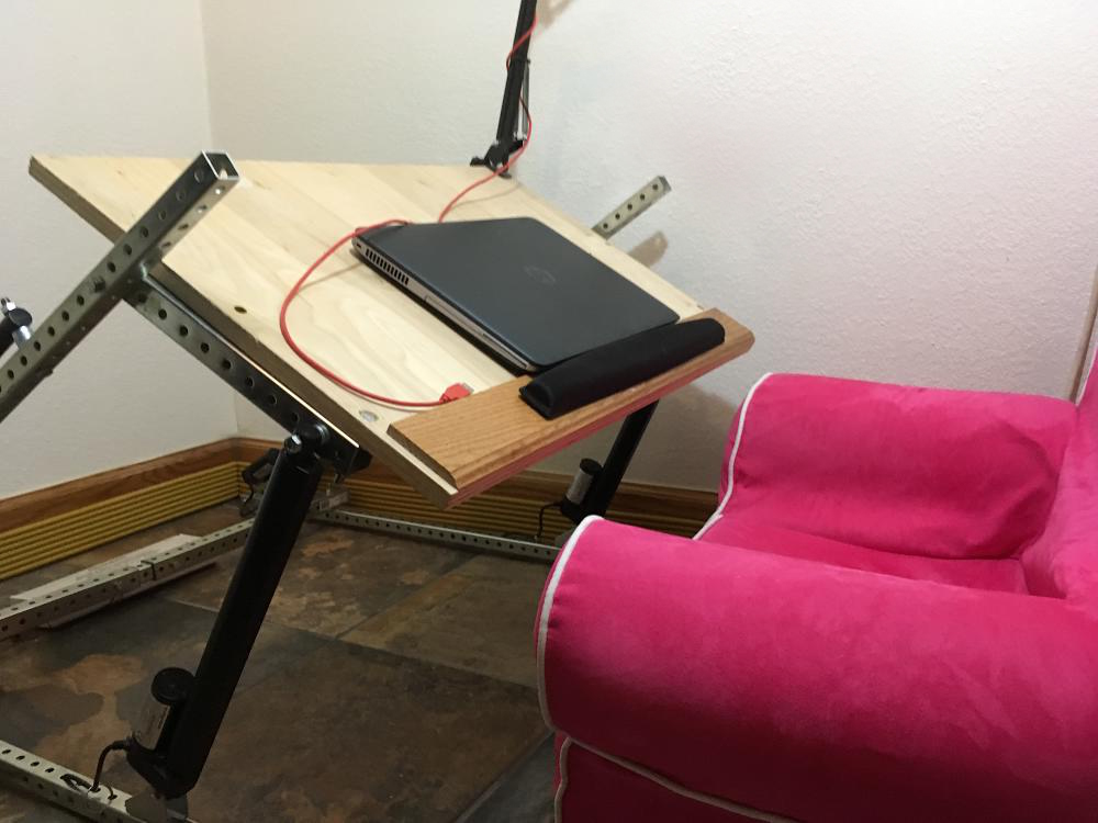
This project originated with a desire to provide more variety in seating positions. I get back pain, and being able to change how I sit seems to help a lot. I used some metal struts from Lowes, and a couple of linear actuators.
That, in combination with
relay kits
and a
wireless controller
completed the project. This is one the simplest projects I’ve built, and one of the most expensive, but my desk is pretty comfortable. The desk in ‘sit on the floor’ mode:
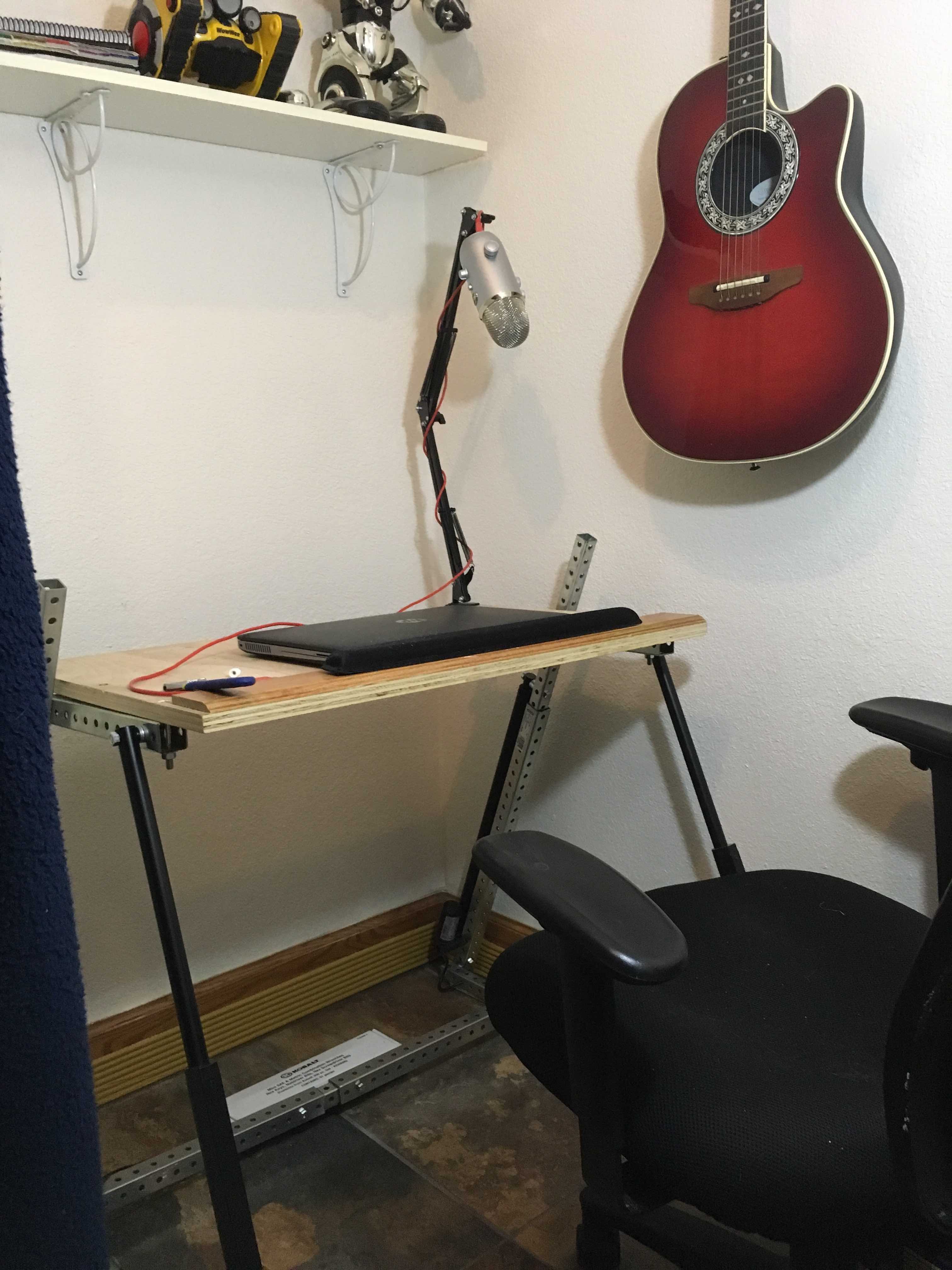
 The desk in ‘sit in the chair’ mode:
wii-motion quad copter
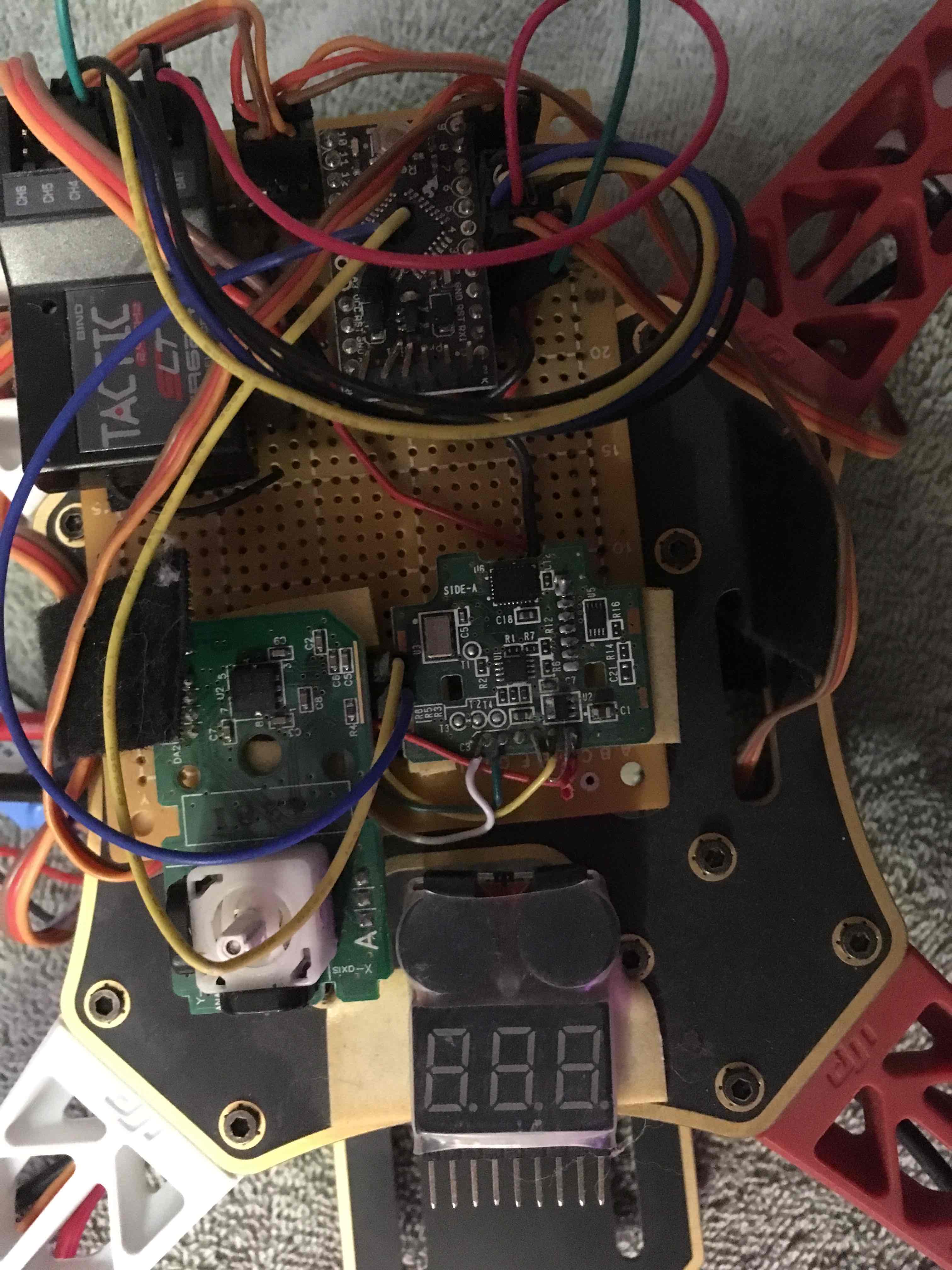
My son and I built this quad copter; the controller is an arduino pro mini; you can learn more about it here.
The MutiWii is built from the gyroscope built into the Wii Motion Plus, and the accelerometer built into the Wii Nunchuck. It was a fun little project, and was actually my first introduction to Arduino. Here’s what the final controller looks like. You can still see the joystick from the nunchuck :)
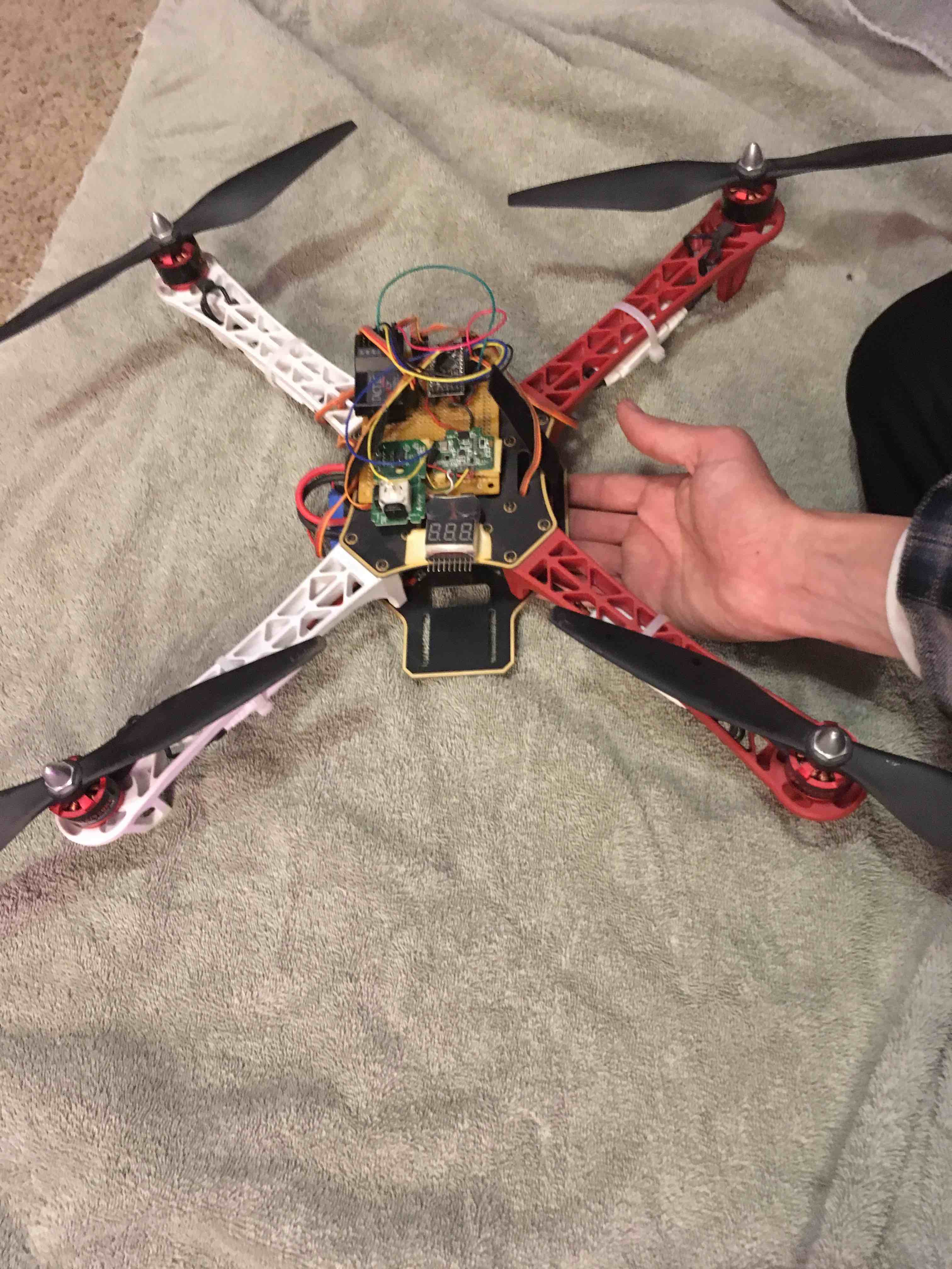
 Here’s a second picture, with my hand, for scale.
Flashing a bricked motherboard bios
A few days ago, a friend asked me to troubleshoot a motherboard that was locking up. I attempted to update the BIOS, and of course, it locked up, effectively bricking the motherboard. A little research, and I found that it was possible to flash the BIOS with the use of a Raspberry PI. I used these links as a reference:
Essentially, you can use a ‘chip clip’ to directly wire into the chip; the chip itself uses the well-known SPI - Serial Peripheral Interface protocol. So, all I needed to do was feed it power, connect to it correctly. Since the motherboard was a brick at this point, there was no harm in giving it a shot. Also, looking at the ‘flashrom’ tool, I didn’t even have to implement any read/write code. All I needed was a solid connection. The guides helpfully pointed me to something called a chip clip, or test clip, which I grabbed off of Sparkfun. This piece is cheaper elsewhere, but I live near Sparkfun headquarters, so I was able to go grab it from them less than 12 hours after ordering it.
The online resources were really good, but they made very generous assumptions about how much I needed things to be spelled out. So I’m documenting the pieces that the above links failed to provide me.
There were two chunks I had to puzzle out. First, most people took pics of the chip clip, connected to the chip on the motherboard, but failed to include a good wiring diagram. Also, my Raspberry PI didn’t have the SPI protocol enabled by default, so I had to do some modifications to get it to even ‘notice’ that it was attached to the BIOS chip.
Wiring everything up. This part was confusing, because I didn’t know how to map the MISO and MOSI ports – which one goes to “SO/SI01”, and which one goes to “SI/SO0”. I eventually found this link that labeled all of the ports; here’s a pic, with what I ended up with; an external power supply, set to 1.5 volts, the chip clip seen in some of the other links, and the flashrom tool.
Here’s a pic of what that looks like 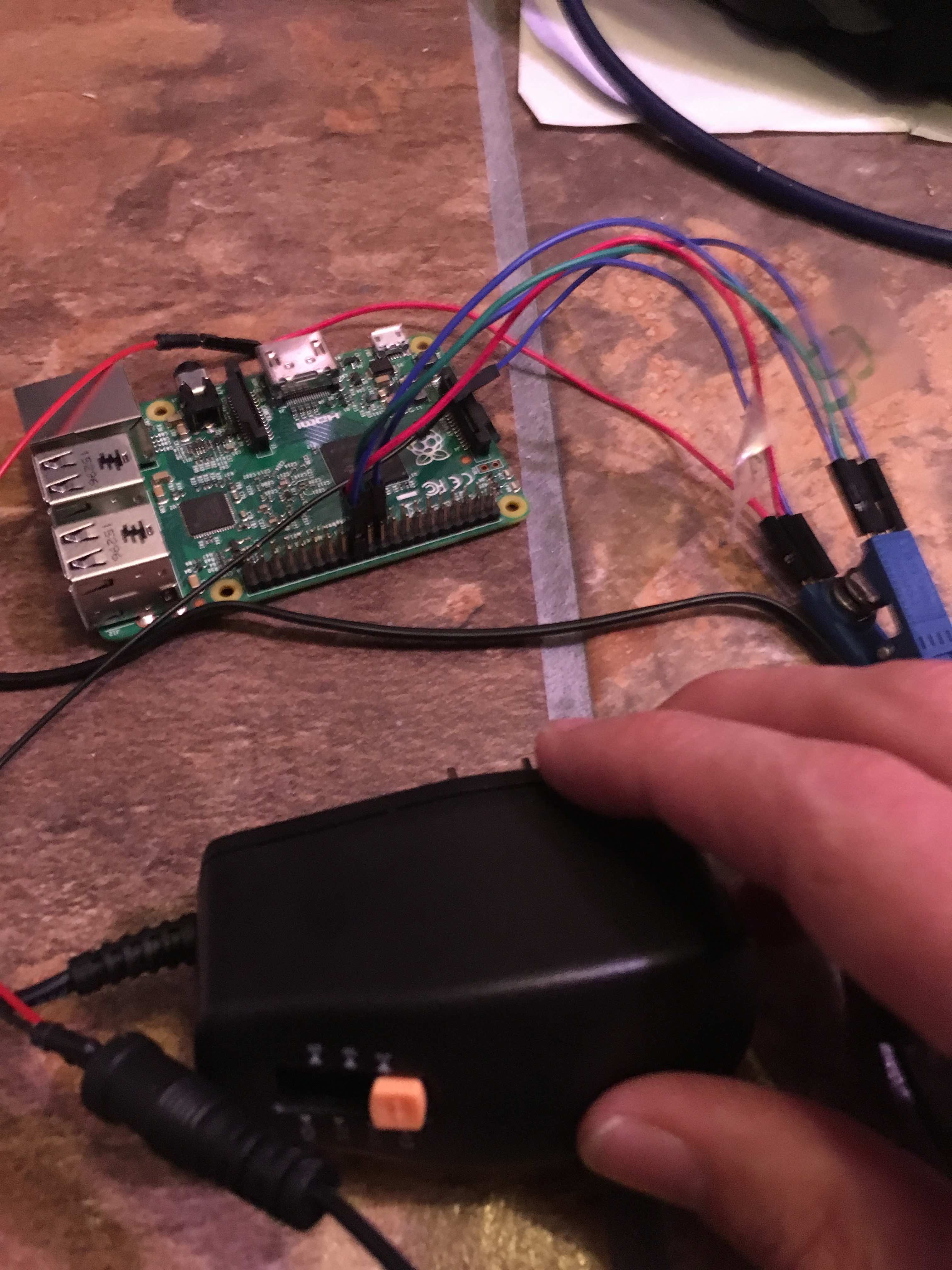
and a wiring diagram, to really spell it out: 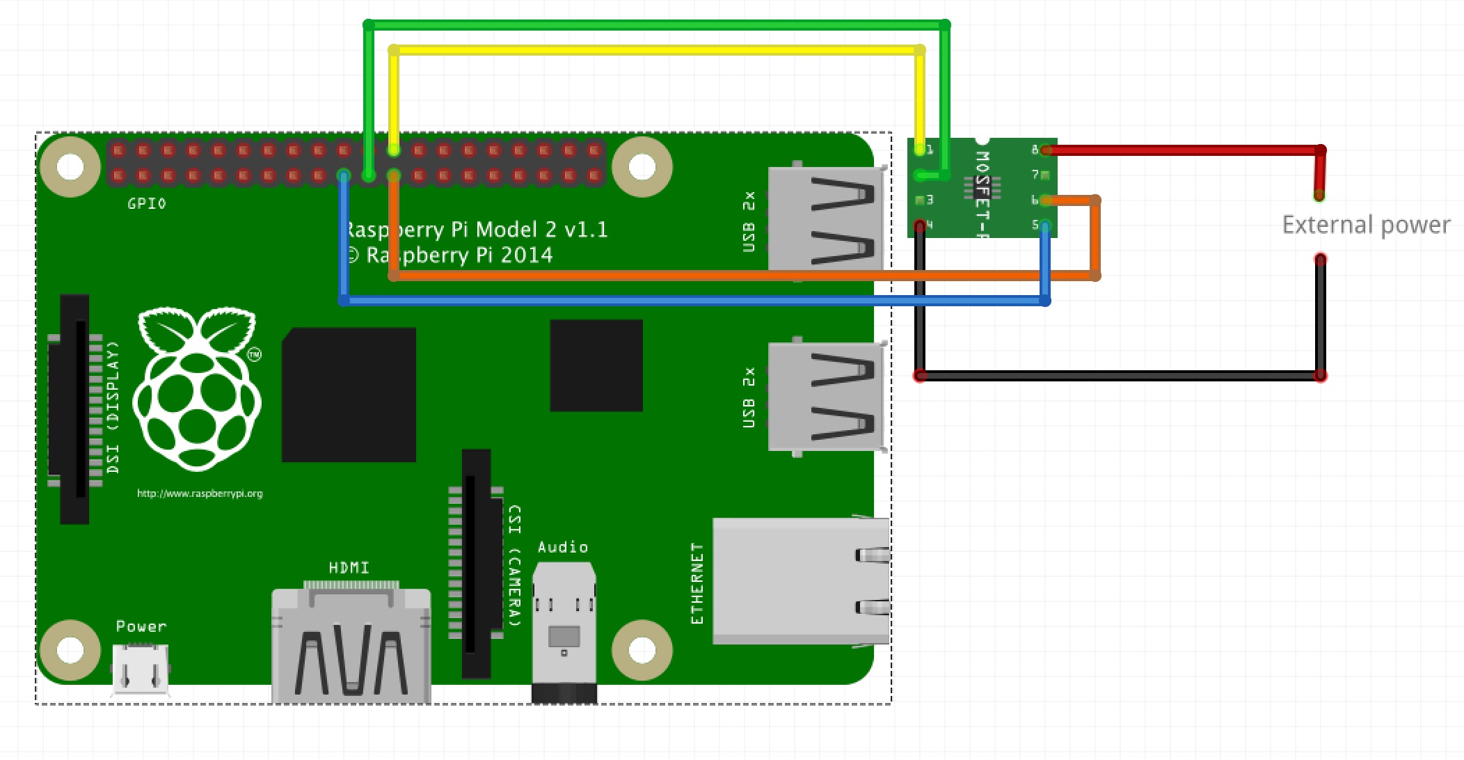
For the Raspberry Pi, I was missing the /dev/spidev0.0 files. Here are the steps I had to take, to make them appear:
sudo apt-get update
sudo apt-get upgrade
- edit the /config.txt file; I had to uncomment the line containing “dtparam=spi=on”, and reboot, which made the spidev files appear.
after that the instructions at the link below worked fine: